Project: Mike's Desk – Completed July 16, 2014
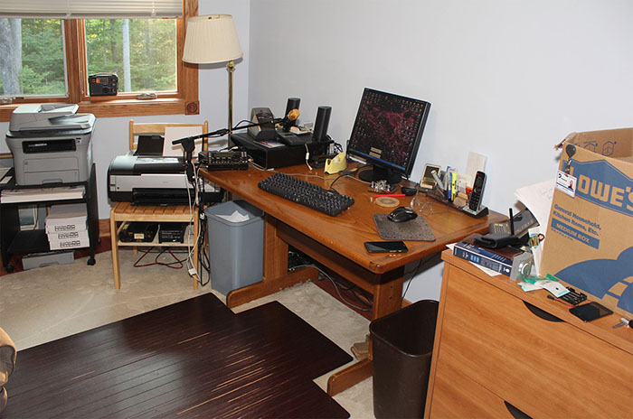
After moving into our new house in January 2011, Mike used a 57" table for a desk, and rummaged through cardboard cartons to find office supplies, as seen below.
After unduring this situation for three years, we built this 10-foot walnut desk. Scroll through this page to see how we did it.
Mike used this table, filing cabinet, printer stand, wooden chair, and cardboard cartons for three years before building the desk.
Building a walnut desk
This page was updated daily during the project, so it reads as though the project is still underway, even though it is now complete.
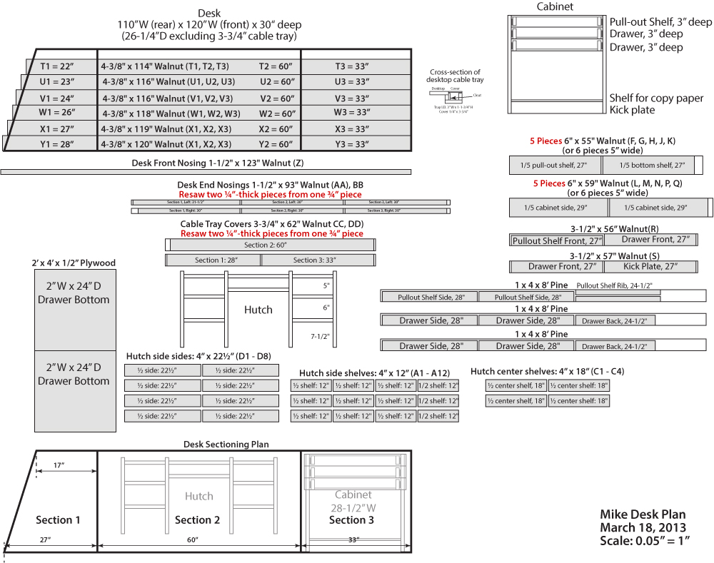
The desk will be 10 feet long, and will be bolted to the wall along the rear. The top will have three sections so we aren't faced with trying to do fine woodworking on 10' boards. A cabinet beneath the right end will have a pull-out shelf for holding papers when we both need to be at the desk, and two drawers for supplies.
This is the overall desk plan showing the lumber needed for the components.
March 16, 2013 – Getting started
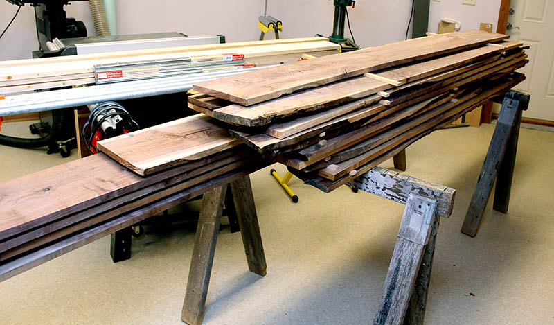
We bought 75 board feet of walnut lumber locally and, after letting it acclimate to our home environment for several weeks, we inventoried it and planned how to cut each board into the needed components. Even though the wood seller surfaced three sides of the rough-sawn lumber, the surfacing is not up to par, and the lumber needs additional work. We have our work cut out for us.
Working the Wood
Our rough-sawn walnut must be cut and milled to the final sizes required. Wide desk parts will be fabricated from edge-glued pieces, as shown on the plan. The boards we received are not exactly the sizes the plan calls for, so Louise inventoried them, then carefully figured which pieces could be cut from each board.
We follow these steps to transform rough-sawn boards into pieces for the desk:
-
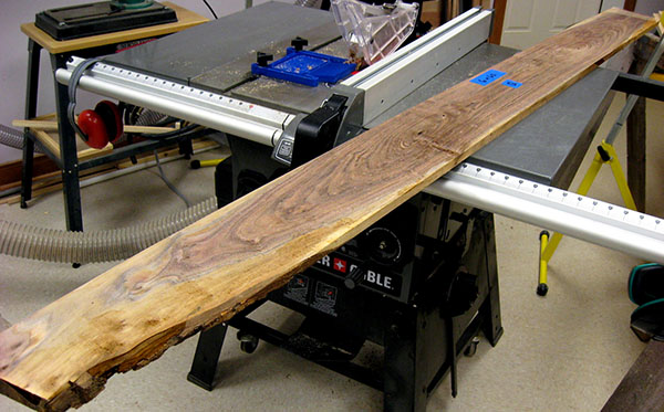
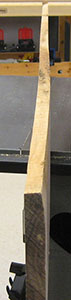
Inspect a board to determine exactly how to cut the required pieces from it. We want to keep as much dark heartwood as possible, and minimize the lighter sapwood. Here is board "Q" on the plan, ready to be transformed into two 6" x 29" pieces for part of a cabinet side. Each side requires five such pieces.
-
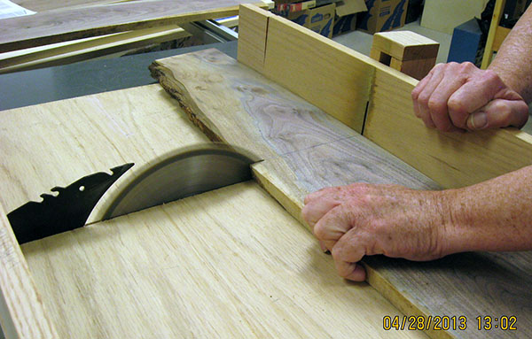
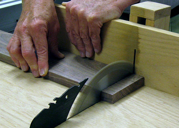
Crosscut the board into the designated pieces, cutting each piece slightly longer than needed. Here, the long "Q" board above has been cut in half, and one piece is being cut to 29½" long, removing the irregular end. (We later salvaged the heartwood from the cutoff, in case we need a small piece later.)
-
Joint the seller-jointed edge to yield a truly smooth edge.
-
With the jointed edge against the table saw fence, rip each piece to be slightly wider than needed, discarding as much light sapwood as possible.
-
Edge-joint each piece until the desired width is reached.
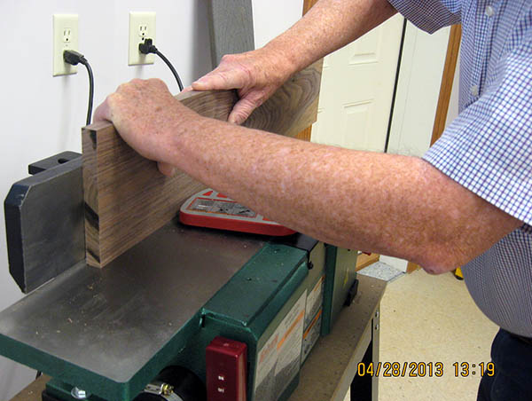
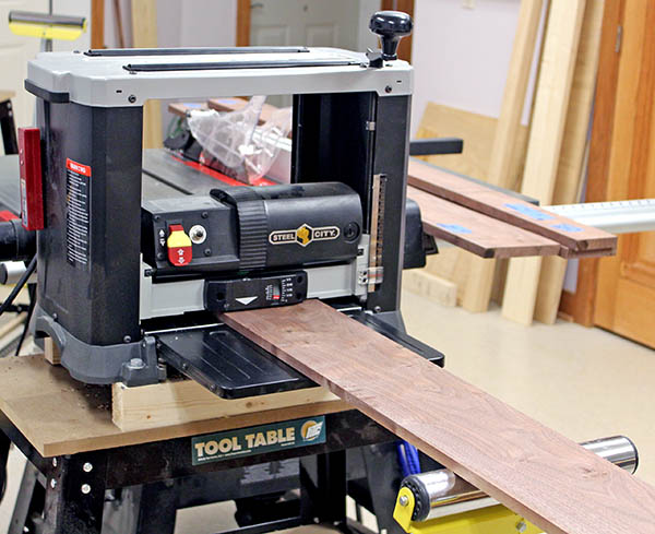
Many desk parts are 27" to 30" wide, so we will fabricate them by edge-gluing narrower boards together. Edge-gluing requires all pieces to be exactly the same thickness. But sometimes, as this photo shows, a rough-sawn board might be warped and/or cupped.
Planing will remove these defects, but such a piece will be thinner than pieces made from straight boards. We must finish all pieces for one part at the same time – the thinnest piece dictates the thickness of all the pieces. Here's how we do that:
-
Crosscut each piece to exactly the length needed. We cut to length first because this operation might leave "whiskers" on the end of a board, but they will be removed by subsequent planing.
-
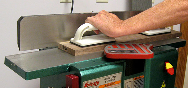
Plane one face of each piece to remove any warp or cupping, yielding one smooth flat surface that is the reference for the next planing operation. This is done on the jointer if the board is short enough to be fully supported by both tables.
-
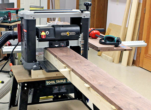
We glue boards longer than 30" to a sled, and run that through the planer to flatten the first face.
-
Run the unfinished face of each piece through the planer to remove any warp or bowing on that side, yielding a second smooth flat surface.
-
Measure the thickness of all pieces for one part, and set the planer to the thinnest in the batch. Plane all pieces in the batch to this thickness so they can be edge-glued. The pieces are now finished, and ready to be assembled into the complete part.
March 24, 2013 – Jointer Problems
Our first boards through a new Grizzly jointer started out with parallel edges, but ended up tapered. This shouldn't be. A jointer is supposed to remove a consistent amount of wood along the entire edge.
First we ripped the board on a table saw to make the edges parallel. We checked the width with a dial caliper at six locations along the length. Typically, the widths were equal to within 0.01". Then we jointed one edge and checked again. Now the leading end was 0.02" narrower, but the trailing end was unchanged – no wood was removed from the trailing end. Repeated passes through the jointer resulted in a seriously-tapered board. Reversing the feed direction resulted in a board with two narrow ends and a hump in the middle.
Clearly, something was wrong. Was it our technique or a defective jointer? The jointer is defective, or at least out of adjustment.
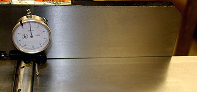
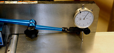
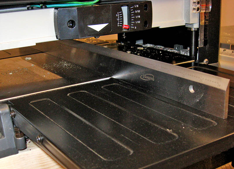
Mike used a machinist's dial indicator to discover the infeed and outfeed tables are not in the same plane ("coplaner"). The outboard end of the infeed table is about 0.02" higher than the blade end. These photos show the measurement setup, with the indicator showing 0.010" midway along the infeed table (the magnetic holder wouldn't reach farther).
Apparently Grizzly agrees with this diagnosis. An email with these photos to tech support brought a prompt response with a return authorization. We'll have to package the jointer, but Grizzly is paying the freight.
This animation illustrates how the tilted infeed table causes the tapered boards. The tilt is exaggerated, but the principle is the same.
At the start, the board is pressed against the tilted infeed table, so wood is removed at an angle from a short portion of the leading end. As the board moves over the cutter head, it is supported by the outfeed table and by the elevated end of the infeed table, causing a tapered cut. Eventually, the board is pressed entirely against the outfeed table (standard jointing technique – no pressure on the infeed table), and the trailing end rises completely off the infeed table and away from the cutter head. No wood is removed past segment #5 above, so the board has a hump.
We proved this by measuring with a caliper, and also by placing the jointed edge on a flat cast iron saw table. The board rocked on the hump, and daylight could be seen under the high end.
The jointer is on its way back to Grizzly. We don't know if we'll get a new one or the same one correctly adjusted. Nor do we know how long we'll have to wait, but this project is on hold for a couple of weeks, at least.

In the meantime, Mike has been reading an excellent book, Understanding Wood Finishing (highly recommended), and experimenting with various techniques. The best he's found so far is:
-
Using artist's arcylic paint, tint water-based grain filler to match the color of our walnut wood. Even though we bought "brown" (vs. "natural") filler, the color was far too light, so the filled grain was colored tan.
-
Fill the wood pores with the grain filler by spraeding it with a putty knife.
-
When dry, sand with 230-grit sandpaper. This removes all filler from the wood surface, leaving the grain pores filled (hopefully) to the same level.
-
Apply a second coat of grain filler, and sand again when dry. First tests showed that not all grain pores were completely filled with one coat.
-
Apply a coat of polyurethane wiping varnish.
-
When the varnish is thoroughly dry, rub with 000 steel wool.
-
Apply a second coat of wiping varnish.
-
When the varnish is thoroughly dry, rub again with 000 and finally with 0000 steel wool. This produces a semi-matte sheen that is somewhat shiny, but not glossy.
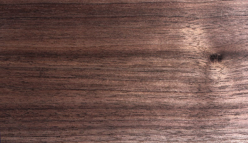
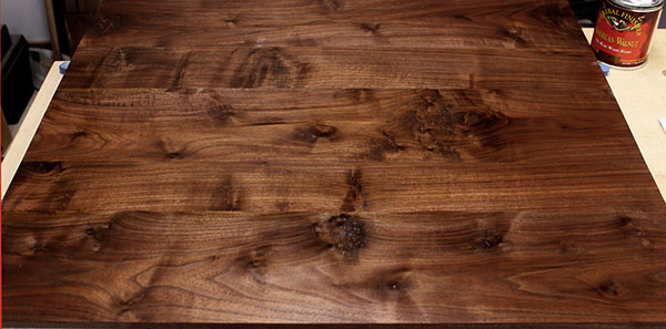
This photo shows the result of the procedure. It looks good and is very smooth, but some open grain remains – noticeable to the touch and visible in reflected light. The open grain is not apparent in this photo, since the filler is colored dark-brown, and this shot is in direct, not reflected, light. We will continue experimenting.
April 13, 2013 – Jointer alignment
We received a replacement jointer a week ago, but its tables were as poorly aligned as the one we sent back. Rather than fool around swapping jointers again, we decided to take a shot at aligning it ourselves – something we probably should have done with the first one.
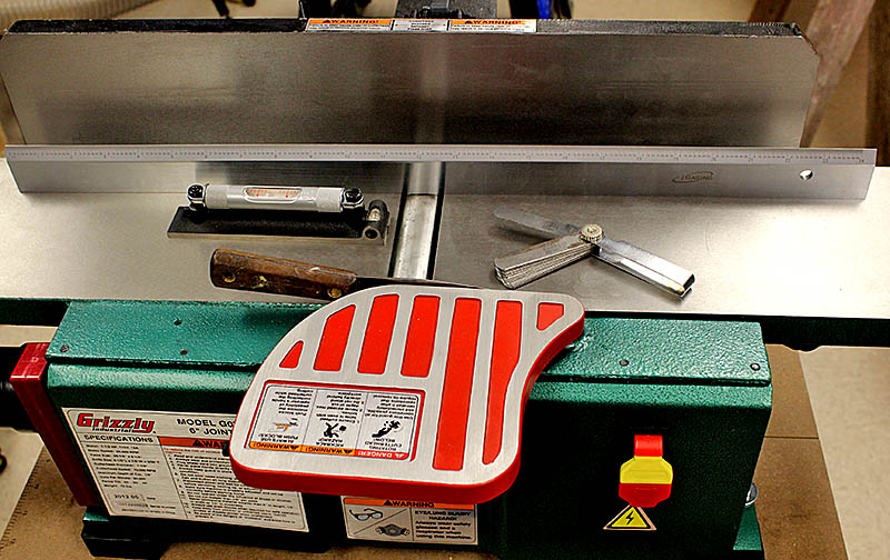
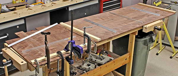
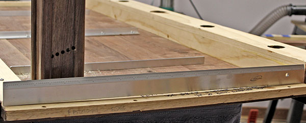
To perform the alignment, we ordered a 24" precision straightedge. This arrived yesterday, so today we made the adjustments. This photo shows the straightedge and feeler gauges, plus a precision level we used for preliminary adjustments.
It looks like our work paid off. There is no sign of taper after edge-jointing our test board. We will proceed carefully, since we're not completely sure of our technique. At least the initial result looks promising.
April 20, 2013 – Planer alignment
After aligning the jointer, it occurred to us to check the planer as well. It's a good thing we did! The infeed and outfeed tables were 0.015" higher than the center table. We used our new precision straightedge and made the necessary adjustments to secure both tables at the correct height.
April 28, 2013 – Back to work
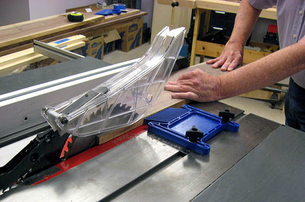
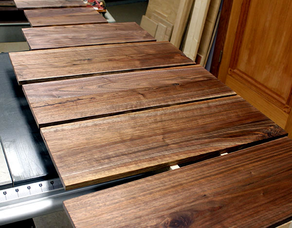
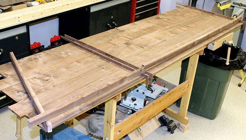
With the jointer and planer adjusted, we finally got to work cutting the rough-sawn lumber into pieces for the desk. After working for several hours yesterday and again today, we are about 40% of the way through cutting pieces to width and approximate length, and jointing both edges. This photo shows the results of our work. When we have all pieces to this state, we'll proceed with the planing operations (steps 6-9 above
).
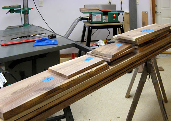
April 29, 2013 – Cutting boards
We cut the remaining pieces for everything but the desk top. Louise referred to her lumber inventory, and marked the boards for cutting. Mike crosscut them on the table saw, then Louise jointed one edge of each piece, and gave them back to Mike. After careful inspection to determine where the good wood was located, Louise marked each piece, and Mike made the first rip cut. (On some pieces, one rip yields the correct width, but other pieces need two rips to remove sapwood or avoid splits, so it pays to plan ahead.)
Oh my! We had one cutoff that looked like it could be used for a spare piece. But during the first rip cut, the saw blade stalled on some tight grain. But the motor did not stall, and proceeded to melt the drive belt!
Fortunately, a Porter-Cable dealer has belts, so Mike ordered three, which should arrive in two or three days.
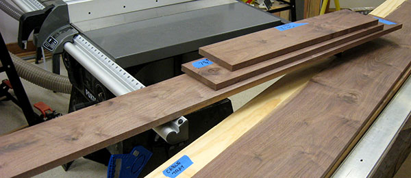
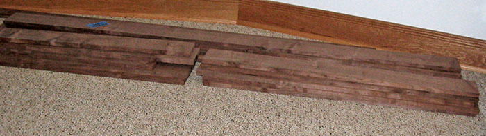
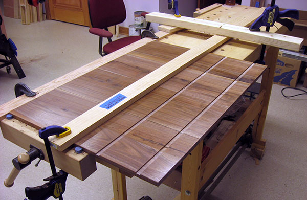
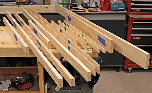
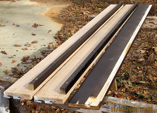
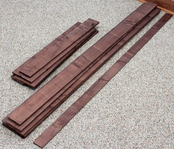
Here is today's batch of pieces after the first rip cut. Once we repair the table saw, we'll rip and joint them to width, and add them to our stock. The five long boards on the bottom are for the desk top, which will be made in three pieces. We'll begin working those boards when we're finished with the shorter pieces.
May 2, 2013 – Saw repair
The replacement belts for the table saw arrived in today's mail, so we spent an hour in the evening cleaning melted rubber from the pulley grooves, then installed one of the belts and reassembled the saw. We expect to resume cutting wood in several days, after taking the weekend to celebrate our younger daughter's college graduation.
May 11, 2013 – Cutting boards again
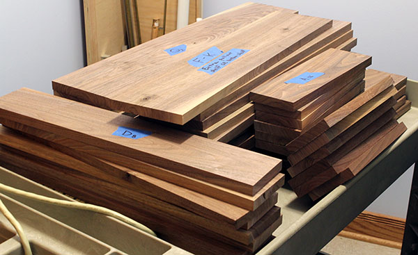
Our "several days" turned into more than a week, but today we got back to work. We finished cutting all the pieces needed for the cabinet, drawers, and hutch. We jointed one edge of each piece, ripped them to width, jointed the other edge, and crosscut them to the exact length.
The only rough-cut lumber remaining is for the three-piece desk top.
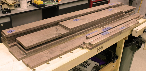
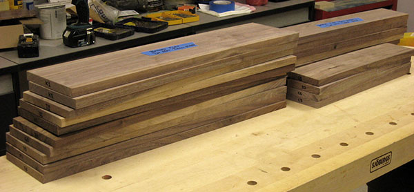
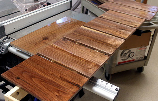
Here is our stock of pieces ready for the next step – planing flat on both sides.
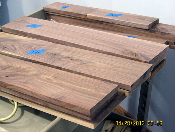
May 12, 2013 – First desk top boards
Today's accomplishment was cutting the first of the five remaining long boards into three pieces for the first row on the 60" center desk top and the two shorter adjoining top sections (see the plan).
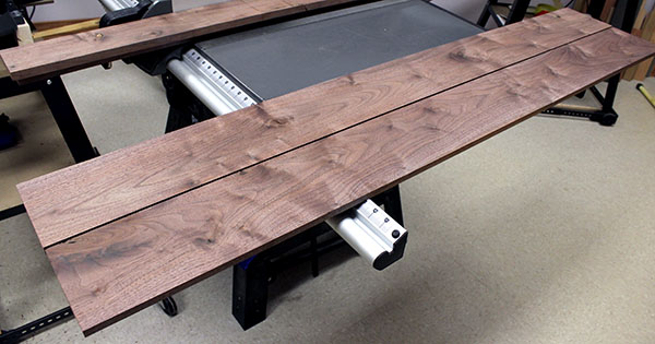
Here are today's three boards.
May 27, 2013 – Desk top boards
We spent the past two weeks cutting desk top boards to width and approximate length. This is a time-consuming process because it is difficult to get a truly straight edge when jointing the 60" pieces for the center section.
The problem is, these boards are too long for our jointer. Even when supporting the overhanging ends on rollers, the board tends to follow any bow or belly along the edge. Mike clamped a straightedge to a board, then used a router with a flush-cut edge-trimming bit to straighten the edge. This worked fairly well, but still required some manual cleanup with a plane and sanding block.
At the end of today, we've cut four of the five long boards into sets of three pieces for the desk top. Only one long board remains.
May 31, 2013 – Board-cutting complete
We cut the final long rough-cut board into three pieces for part of the desk top, plus some narrow strips for desk nosing. All the rough-cut lumber has been ripped to width, edge-jointed, and cut to length. The next step is to plane one surface flat on all boards, using the jointer, then plane the opposite surface flat using the planer. When using the planer, we must be sure to work all boards for each desk component using exactly the same thickness setting on the planer, so they will have an even surface when edge-glued together.
Here are the boards for the three sections of the desk top, with the nosing pieces along the front of the workbench.
June 2, 2013 – Planing sled
Once again we found the tables on our jointer are too short to accurately plane one surface flat on boards longer than about 28". Mike did some research online (the Internet is wonderful!) and came across the idea of making a "sled" to hold the board as it travels through the planer.
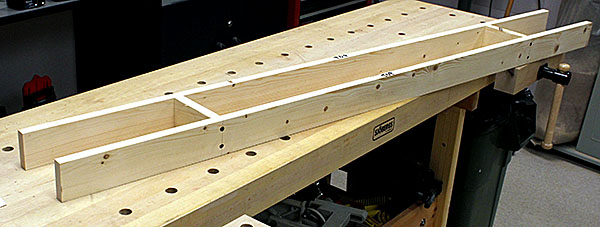
This is Mike's sled, made from pine boards, and run through the planer to create flat top and bottom edges.
June 4, 2013 – Planing the boards
With the planing sled built, we began the process of flattening the boards. These photos show thow we process each long board, and shorter boards if they are severely warped.
A walnut board is placed on top of the sled and shimmed until it doesn't rock, then glued to the sled using tiny dabs of Gorilla Glue.
When the glue is dry, the sled and board together are sent through the planer several times to remove humps and warps. Once the board's surface is level, the glue bonds are cut with a putty knife (Gorilla Glue foams, so it is easy to slice).
Then the board is removed from the sled, flipped over, and sent through the planer again. The flat surface now on the bottom is the reference for flattening the opposite surface.
Planing this second surface also removes residue left from being glued to the sled. In the final step, we send the sled itself through the planer to remove glue residue and provide a fresh flat surface for the next walnut board.
Glue a board to the sled

Plane the top of the board on the sled
Remove the board from the sled, flip it over, plane the opposite surface
Our first two good boards, four sides surfaced, 62" long
June 16, 2013 – Planing more long boards
Yesterday and today we planed two more of the 62" boards for the desk top on the planing sled. Four long boards are finished, and only two more remain. After we finish them, we can plane the short boards on the jointer and planer without using the sled.
June 20, 2013 – Cable tray covers
The desk will have a tray along the rear to hold computer cables, with thin walnut boards covering it. We used the band saw to "resaw" a ½"-thick board in half to make two ¼" boards.
Resawing means cutting a board through its thickness to make thinner boards, instead of cutting it to length (crosscut) or width (rip). When resawing, the board is fed through the band saw on edge. With this technique, multiple thin boards can be cut from one piece of wood. Here the blade is cutting a ¼" slice from a 5/8" board. The yellow featherboard presses the wood tightly against the fence to ensure a straight and even cut.
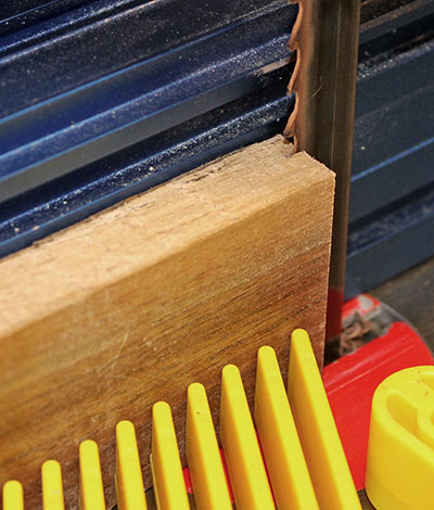
Planing reduced the tray cover boards to 3/16" thick. Here they are, ready for 1½" holes to be bored in them, then sanded and finished. We will set these 5-foot pieces aside until the desk is built.

July 2, 2013 – Planing desk top boards
After 12 days off, we got back to planing boards for the desk top. The five long center-section boards are done, so we planed the 10 short boards that will abut each end of the center section. Being only about 30" long, we could use the jointer to flatten one face, then run them through the planer to flatten the opposite face.
All the desk top boards are planed, although not to their final thickness. Today's 10 boards are shown in front of the five long center-section boards. We store all planed boards on the floor to keep them flat.
Mike used the jointer to plane flat one surface on 32 "short" boards. Boards 30" or shorter are supported by both tables on our jointer, so it's fairly easy to eyeball any warp or cup, then feed a board through the jointer to flatten that surface.
Here are 22 of today's boards. Only a dozen 12" pieces remain to be planed on the jointer. After that, all boards must be run through the planer for final thickness-planing.
July 4, 2013 – Hutch side shelves
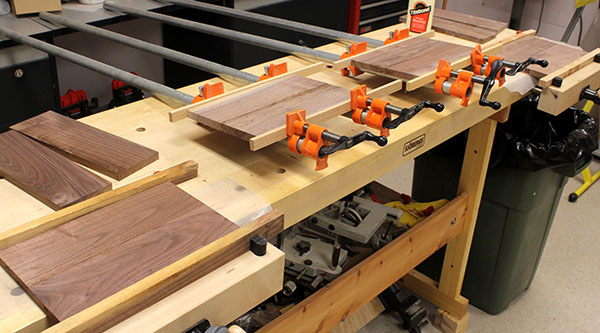
Mike planed the second surface flat on the dozen 4"x12" boards for the six hutch side shelves. Then we measured the thinnest board and planed all of them to this thickness. Finally, we edge-glued pairs of boards together to make six 8" shelves (four shown clamped in this photo).
July 5, 2013 – Hutch center shelves
Mike continued yesterday's work, and planed the second surface on the four 4"x18" boards for the two hutch center shelves. As before, he planed all four of them to the thickness of the thinnest bord, then edge-glued pairs of boards together to make two 8" shelves.
When the glue has cured, we will plane these two center shelves and yesterday's six side shelves to a final thickness of ½", preparing them to be installed in ½" dados (slots) cut into the hutch sides.
July 6, 2013 – Cabinet shelves
The cabinet on the right side of the desk will have two drawers plus a pull-out shelf for guests, and a lower shelf to hold reams of printer paper. Each shelf consists of five 6" x 28" edge-glued boards.
The ten boards were planed flat on one face several days ago, so today we planed the opposite face to make them all the same thickness. Each shelf will be 30" wide, which is too wide for our planer, so we must glue pairs of boards together, then run each pair through the planer to reach the final thickness. Once all the boards are planed, we will glue sections together, and remove excess glue by scraping and sanding.
Here 10 boards are stacked in the foreground, while two others are being glued in the pipe clamps.

July 7, 2013 – Hutch and cabinet sides
Gluing pairs of boards together for cabinet shelves takes time because we allow at least six hours for the glue to dry. In the meantime, today we planed boards for the hutch and cabinet sides. The four hutch sides are made of pairs of 4"x22" boards. We planed these eight boards to their final thickness, and they are ready to edge-glue when the pipe clamps become available.
The cabinet sides are similar to the cabinet shelves, each comprising five 6"x29" boards. We planed these 10 boards close to their final thickness so we can edge-glue pairs of them, similar to the shelves. Then we will plane the boards to their final thickness, and glue them into the full-width sides.
July 10, 2013 – Hutch sides
Yesterday we paired boards for the hutch sides and began edge-gluing them. We can glue only two pairs per day because we allow at least six hours for the glue to cure. Today Mike glued the final two pairs, so tomorrow they will be ready for final planing.
July 11, 2013 – Needed supplies
Excellent! Today we received a ½" router bit we've waiting for. This will be used to rout slots for shelves in the hutch and cabinet sides. We can't plane these shelves to their final thickness until we know exactly how wide the slots will be. Tomorrow we will rout a test slot on a scrap of walnut, and measure it.
In the same package were two containers of wood filler, one colored dark and one light. Now we can fill any voids in boards before planing them to the final thickness.
July 13, 2013 – Planer adjustment
Yesterday Mike cut a test groove for shelves in a scrap of walnut, using the new ½" router bit. He measured the slot width (0.501") and planed another scrap to just a tad thinner than this. We plan to finish the shelves before assembling them into the slots, so Mike started the finishing process on the "shelf" scrap. He will check the final thickness when the finish is dry.
We noticed boards planed recently have a shallow ridge running the entire length. This indicates a problem with the planer's cutter head. Our planer has a helical cutter head with 26 small blades, instead of two or three blades that are the entire 13" width.
We dug into the planer and discovered one blade's edge was slightly deformed and dull. Perhaps it hit a knot. We rotated this blade to its second cutting edge, but the ridge still showed up, albeit with a slightly different shape. We decided to remove and rotate the remaining 25 blades, cleaning their mounting platforms and alignment stops to remove accumulated dust. After this procedure, the planer again produces smooth boards.
July 19, 2013 – Planing progress
Sadly, the new edges on the planer blades (above) didn't last very long. After a couple of boards went through with good results, the ridges reappeared. Mike concluded the tool-steel blades couldn't handle beads of dried wood glue where boards were edge-glued.
We ordered 30 carbide blades, and today we replaced the original blades with 26 of these. When we removed the original blades, we found two of them were severely blunted. Since these were in the area of the glue bead on wide boards, it appears the glue did indeed ruin the blades.
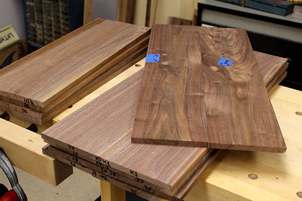
With the new blades installed, planed boards came out nice and smooth, with no sign of the ridge. in this photo, four edge-glued hutch sides on the left are ready to be finished and have grooves cut for shelves. The four pairs of edge-glued boards on the right are for cabinet shelves. These will be edge-glued with the two single boards angled on top of the stack to create two shelves approximately 29" wide. (The blue tape indicates small areas of wood filler that must be sanded.)
July 20, 2013 – Initial finishing
Mike applied grain filler to both sides of two hutch sides. When dry, he sanded the boards with 220-grit aluminum oxide sandpaper to remove the excess filler and expose the bare walnut.
This is the first of several finishing steps. After the grain pores are filled, we will apply several coats of polyurethane varnish, sanding between each. We're finishing the pieces prior to assembly to void sanding in tight corners.
July 26, 2013 – Finishing hutch shelves
Mike has spent several days applying grain filler to three hutch shelves, then sanding them emooth and applying varnish as the initial finish coat. sanding the grain filler flush with the wood surface is a slow and tedius process, so Mike tried using a random-orbit power sander. This produced a huge cloud or dust, so he reduced the tool's speed and mounted the sandpaper disk so the holes were not aligned with the holes in the tool. This prevents the tool from vacuuming the dust and clogging the filter. All of the dust remains on the wood, and we brush it off later.
We have no photos of this work, but the shelves are turning out nicely.
August 1, 2013 – Finishing hutch shelves
Several days ago we applied grain filler to the remaining hutch shelves, and today we sanded it smooth to the wood surface. We wiped the boards with solvent, then wiped on a coat of thin polyurethane varnish to provide a base coat for subsequent coats of regular varnish. Here are some of the boards drying on the planing sled.
August 16, 2013 – Finishing hutch parts
We took some time off, but in recent days we have been finishing sides and shelves for the hutch. After today's work, all parts have at least two coats of wiping varnish on both sides, and most of them have the final finish coat as well. The shelves have a finish coat on top, and a close-to-finish coat on the bottom. The sides need a finish coat on both surfaces, so tomorrow we'll apply one more coat where needed.
Here are most of the boards we did today, waiting for the varnish to dry.
August 27, 2013 – Hutch side routing
The hutch boards are finally finished with three coats of wiping varnish rubbed with #0000 steel wool to a satin finish. Today we routed slots in the sides for shelves.
To ensure accuracy, we clamped all four hutch sides to the workbench, then clamped a straightedge over them. One pass with the router yielded a perfect ½" slot in all four sides.
Next step: dry-fit the hutch and measure for the backing board, then cut and finish that piece. After that, we can build the hutch.
August 28, 2013 – Hutch dry-fit
Mike dry-fitted the hutch on the workbench, then measured and cut the backer board. Last, he stained the rear of the board to check for a good color match with the real walnut hutch.
Later. . . . The color didn't match well, so we chose a darker walnut stain, and Mike stained the front of the backer board.
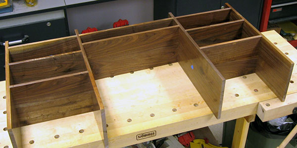
August 29, 2013 – Hutch assembly
We glued the hutch together in two steps. First, we assembled and glued the left and right end sections and clamped them using vises at the ends of the workbench and pipe clamps on top.
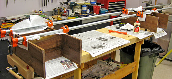
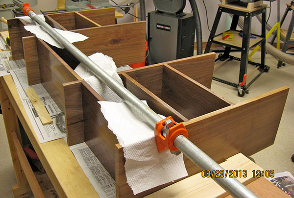
When the glued ends were dry, we applied glue in the slots for the center shelves, then assembled them between the end sections. We measured carefully to ensure everything was square, then tightened the bench vises and the one pipe clamp.
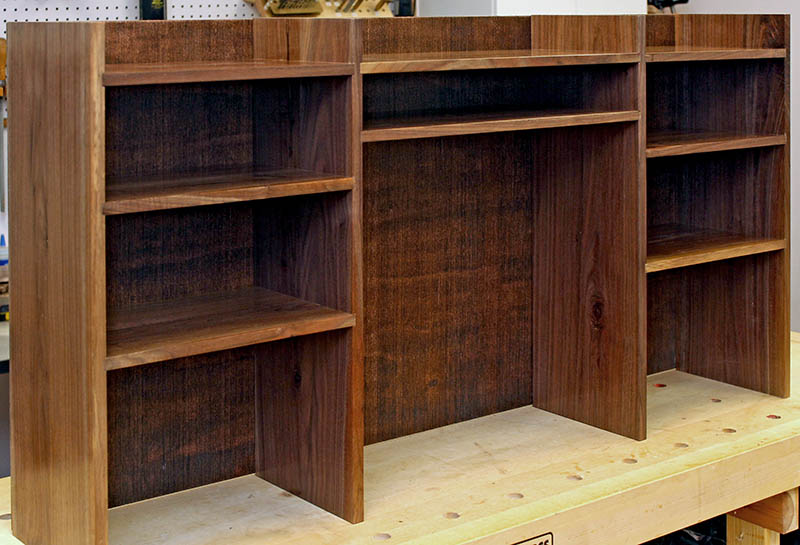
August 31, 2013 – Hutch complete!
Today we glued and pinned the backer board to the hutch.
One remaining job is to fashion four trim pieces to cap the top end-grain on the side pieces. These were not planned, but they'll make the hutch look more finished. It's a minor task, involving jointing one edge on a scrap board, then slicing-off a thin strip. Repeat four times, cut the strips to length, sand smooth, finish, and glue them on.
September 1, 2013 – Hutch caps
Mike made the end-grain caps for the hutch, and they turned out as well as hoped.

September 5, 2013 – Gluing cabinet shelves
Two days ago, we edge-glued the first of two shelves for the cabinet, and today we glued the second. We use pipe clamps across the boards, and small clamps on the ends of joints to ensure the surfaces are flush. This shelf consists of two 12"-wide boards that were edge-glued back in July, plus a 6" center board.
September 9, 2013 – Gluing cabinet sides
Today we planed to the same final thickness the 10 boards that will become the cabinet sides. Then we edge-glued two pairs of boards. Two pairs remain to be glued. The two sides will each comprise two pairs plus one individual board edge-glued together.
September 20, 2013 – Cabinet panels and drawer pulls
We have complete edge-glued panels for the cabinet sides, cabinet top, cabinet bottom shelf, and cabinet pull-out shelf. We spent a couple of hours today planning the cabinet and figuring dimensions of the shelves and drawers.
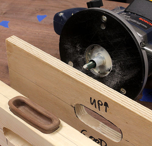
Later, Mike made a template from ¾" plywood to guide the router when cutting recesses for walnut pulls in the drawer fronts. This photo shows a pull resting in a test hole, with the template and router behind.
September 21, 2013 – Cabinet work
We got a lot done in two hours today. We measured and routed holes for the pulls in the front boards for the drawer and the pull-out shelf. This photo shows the fronts with the empty holes, and the pulls test-fit into the holes. (This is an oblique shot; all holes and all pulls are actually the same size.)
With the drawer pulls under control, we cut the pull-out shelf to its final size. Then we cut and stained two pine rails that will hold the full-suspension slides for the pull-out shelf. After that, we filled about 18 blemishes and rough grain in the desk top that will fasten to the cabinet.
September 23, 2013 – Struggling with wood filler
It's hard to believe this project has been halted by something as trivial as wood filler. The walnut has various blemishes, ranging from tear-out from machining to rough end-grain in knots and elsewhere. Our plan was to fill these blemishes with a highly-recommended (by the Woodcraft store personnel) filler. We bought a sample size of "natural" color, but it was far too light. So we bought full-size containers of "walnut" (dark brown) and "ebony" (pure black).
The "walnut" spread on nicely, and matched the wood fairly well, but when we sanded the dried filler, it turned the same color as the "natural!" We tried mixing "ebony" with the "walnut" in various proportions, but that also lightened drastically when sanded. The pure "ebony" turned medium-gray when sanded.
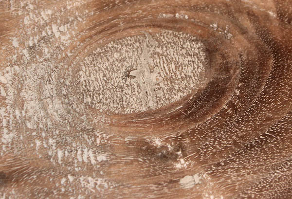
This photo illustrates the problem. The knot has rough end-grain, so we spread a layer of filler over it, and let it dry. We started with "walnut" and "ebony" filler mixed about 60/40 to darken it but still keep the brown tint. When we applied the filler, it was very dark brown – darker than the portion of the knot at the 4:00 o'clock position. Look at how light it became during sanding! This is the color of the "natural" filler.
We can't use this filler, so tomorrow we'll call Woodcraft to ask for advice and see if they'll give us a partial refund. Maybe there is a different brand that will retain its color.
September 27, 2013 – Wood filler solution?
Three days ago we visited the Woodcraft store with the cabinet desk top panel, to show the problems we are having with wood filler lightening after sanding. One of the experts there claimed the filler will return to its original color when dampened with mineral spirits or shellac. He demonstrated this on the bottom side of the panel and, sure enough, it turned dark and remained dark after the shellac dried. He also demonstrated two types of stain that can be used to darken the filler (and the wood) further, to make color variations less noticeable and still provide a rich finish. We bought a bag of dewaxed shellac chips and the two stains. Hopefully these will solve our problems.
This "before" photo shows the cabinet desk top panel after the wood filler was sanded. The light areas are the wood filler.

September 28, 2013 – So far, so good
Mike sanded the cabinet desk top panel, then wiped it with a paper towel dampened with mineral spirits. When this dried, he wiped on a thin coat of shellac. This photo shows the result – the light wood filler has darkened, and the filled areas are not so noticeable. Our next decision is whether to apply stain to darken everything slightly and make it blend together more.
The shellac raised the grain in several areas on the cabinet desk top, so Mike used 400-grit sandpaper in a power sander to smooth it. Fortunately, sanding didn't lighten the wood filler. Next he wiped-on a coat of "American Walnut" stain. This darkened the panel slightly, and helped visually blend the wood filler with the surrounding wood.
This photo shows the stained panel. In particular notice now the two light bands of sapwood on the left side of the panel above are less noticeable after staining. This required some careful wiping of stain only in the light areas, then more careful wiping to remove excess and blend the edges.
October 2, 2013 – desk top nosings
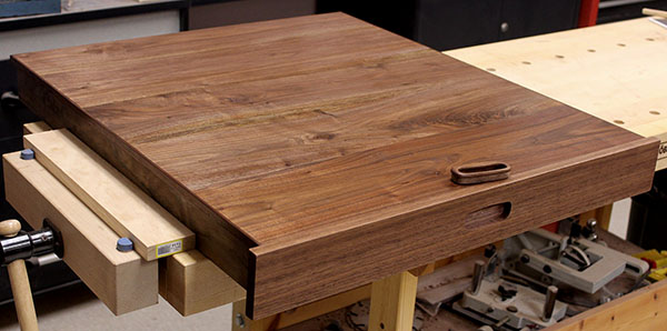
With the cabinet desk top panel under control, Mike worked on nosings for all the desk top panels' edges. The front edge and visible ends of the panels will have a ¾"-thick nosing 1½" tall, with rounded top and bottom edges. The ends that butt against adjacent panels will have 1/8"-thick nosings just a bit taller than the panel thickness (they'll extend below the panel, not project above it).
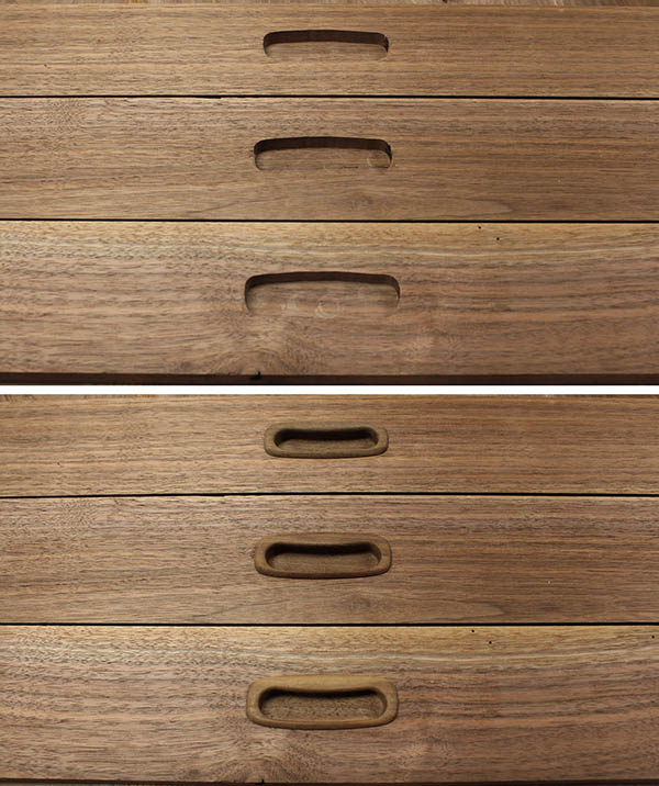
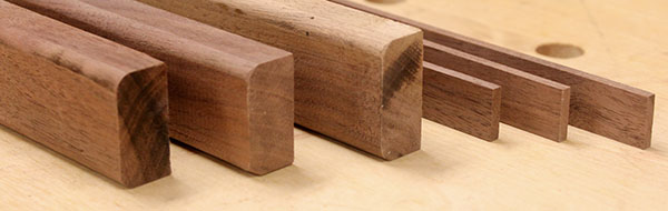
This photo shows three visible nosings with ¼" radius rounded edges, plus three hidden "butt" nosings. Only the top edge of the hidden nosings will be visible. All nosings are longer than needed, so any defects on the ends will be cut off.
October 6, 2013 – Pull-out shelf
Mike worked on the pull-out shelf over the past several days. He cut and planed two 1/8"-thick by ½"-tall nosings to cover the end grain on the shelf sides. He drilled holes to attach metal drawer slides to two ¾" pine rails on the shelf bottom, one on each side, then he glued them on. Finally, he glued the previously cut front board to the shelf assembly. After final sanding and wiping with mineral spirits, Mike wiped-on a coat of shellac. When that dried, he applied a medium-brown stain over the whole shelf to darken and blend the light sapwood areas. When that was dry, he applied a darker stain to sapwood that was still too light.
This is the shelf with shellac, but before staining. Notice the light sapwood bands, especially at the center-left. (The right half of the shelf is brighter due to overhead shop light reflections, so that sapwood appears lighter than it really is.)
With a different camera angle to minimize reflections, here is the shelf after staining. The sapwood now is much less noticeable. The remaining task is to apply several coats of wiping varnish for the final finish.
October 12, 2013 – The cabinet desk top looks great!
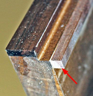
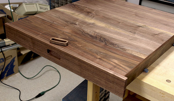
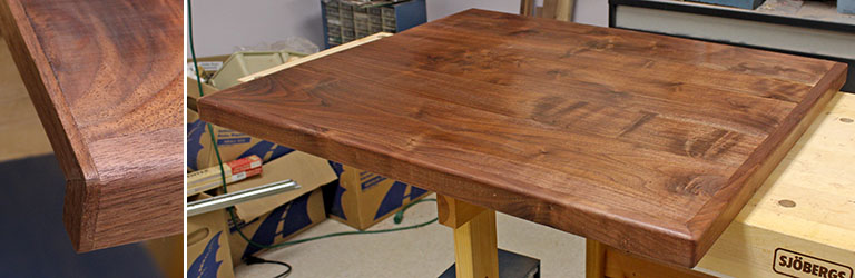
Mike glued and sanded the nosings on the front and right edges, followed by a 1/8"-thick nosing on the left side, where this piece will adjoin the main desk top. This thin nosing is shown in the left detail photo. Mike mitered and glued two pieces into an "L" shape, so end grain cannot be seen. The grain runs along the panel edge, and turns downward at the front nosing.
The main photo shows the complete desk top. The nosing gives the panel a substantial look, and disguises that it is only ½" thick.
October 14, 2013 – First drawer built
Yesterday Mike cut the sides and bottom for the two drawers in the cabinet. The drawer fronts are walnut, but the sides are made of select pine. The bottom is 5mm luan plywood. The rear board is glued into rabbets cut into the ends of the side pieces. The front board is glued to the butt-end of each side, and the these end-grain joints are reinforced with a small strip of wood glued inside each corner. The bottom panel is captured by a groove in all four sides, and is not glued.
No screws are used in the drawer construction, since wood glue alone is strong enough for this light-duty application. The drawer sides and bottom are finished with a coat of varnish, and remain their natural color. The front is finished like all other walnut – shellac, stain, and several coats of wiping varnish.
Here is the complete 2' x 2' drawer with the front and sides for the second drawer resting in it. The side board on top of the stack shows the bottom groove and the rabbet for the rear board.
October 15, 2013 – Both drawers built
Mike assembled the second drawer and applied shellac and stain to the front. All that remains is to varnsh the walnut, add the pulls, and attach the full-extension slides.
October 18, 2013 – Varnishing the drawers
Mike made good progress over the past few days varnishing the pull-out shelf and the drawer fronts. So far, he has applied three coats of wiping varnish to the shelf top and front, and two coats to the drawer fronts. He smooths the dry varnish by rubbing with 0000 steel wool. Three coats of the thin varnish probably are enough, but he might go to four.
October 19, 2013 – Drawers complete
Mike applied the final coat of varnish to the pull-out shelf and drawers, then moothed it to a matte finish with steel wool. He glued the pulls to all three fronts, and these components are complete, and ready for their metal slides.
Next up: Build the cabinet and install the shelf and drawers.
October 24, 2013 – Cable tray parts
The desk will have a tray along its rear edge to hold computer cables and power cords. After considerable measuring and planning, Mike produced two drawings, and cut the pine for the cable trays on all three desk sections.
Our router and router table aren't up to the task of cutting precise rabbets, so Louise came up with the excellent idea of gluing a thin strip of wood to the tray sides to create the ledge needed to hold the walnut tray cover. Here are the tray parts after planing to the fairly precise dimensions needed for the cover to rest flush with the desk top. The thin boards will be glued to the sides to create the ledges.
October 26, 2013 – Cable trays
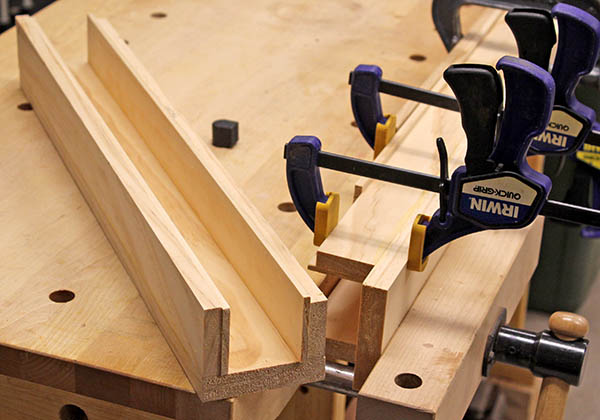
Yesterday Mike discovered he hadn't planed several cable tray parts to the right thickness, so he corrected that. Today he glued the parts for the desk top extension (left end) cable tray, and together we both glued the parts for the main section (clamped in photo).
October 28, 2013 – Cable trays finished
With the cable trays fabricated, Mike cut and planed thin ½"-wide walnut trim strips for the rear side.
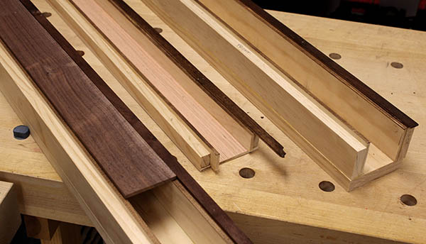
This photo shows how the walnut cover will rest on the tray ledges between the desk top and the trim strip. The front of the cable trays will be glued to the underside of their respective desk tops. The desk top, cover, and trim strip all are in the same plane.
The shallow tray in ghe center is for the cabinet, where the pull-out shelf must slide beneath it. All cable trays are longer than needed, so the excess wood overhanging the ends will be gone once the desk top sections are complete and the trays are cut to length.
November 5, 2013 – Cabinet asembly setup
Mike began preparing the cabinet sides for assembly. A few days ago he routed a slot in each side panel for the lower shelf. Unfortunately, the guide board for the router shifted partway through the process, so the slot wavered. To recover, we moved the guide upward about ¼" and routed the slot wider, and straight on top. The shelf will be upported by aluminum angle rails below, forcing it upward against the straight top of the slot.
This photo shows a ½"-thick stand-in for the shelf, an angle rail, and matching holes in the cabinet side. It is vital that screw holes do not break through the good side of the wood, so Mike machined a Delrin stop for the drill bit (foreground). The set screw holds the stop in place on the bit, and the bit is inserted into the drill chuck until the stop touches the jaws. This provides a positive depth limit – the drill can't possibly go any deeper.
November 7, 2013 – Cabinet asembly setup
Yesterday we cut the cabinet side panels and the bottom shelf to their final dimensions, and cut off half an inch of the pull-out shelf so it will fit inside the cabinet. The next step is to drill mounting holes for the drawer slides.
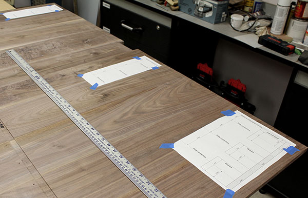
Mike used Adobe Illustrator to create a template showing the pull-out shelf and drawers relative to the cabinet desk top. We used this to verify the planned 1/8" space between drawer fronts is really what we want. The template also shows the centerline where holes for the drawer slides are already drilled in the shelf and drawer sides.
He printed three copies of the tamplate, and taped them to the cabinet sides, precisely aligned with the line representing the bottom of the desk top nosing. Then he transferred the drawer slide centerlines to the cabinet sides. Next he will lay the slides over the lines and mark the mounting holes, then drill with the limited-depth bit.
November 10, 2013 – Cabinet panel finishing
Yesterday Mike sanded the cabinet bottom shelf, and spread grain filler on the top surface. Today he scraped and sanded the excess filler off, leaving the wood pores filled flush with the surface. Later he applied a coat of shellac, sanded that smooth, and wiped on a coat of wiping varnish, one of three coats that will be applied.
The bottom shelf is in the foreground, and one of the cabinet sides is behind it, ready to have its edges masked, and grain filler applied. The sides need to have their grain filled on both surfaces, since both will be visible, and grain filler yields a smooth finish.
November 13, 2013 – Filling the grain
Mike applied one more coat of wiping varnish to the cabinet bottom shelf, then spread grain filler on the exterior faces of the cabinet sides.
Grain filler is a soupy mixture spread with a hard rubber blade, diagonally to the grain, to force the filler into the grain pores. When dry, the filler forms a tan chalky skin that must be removed to reveal the wood.
This photo shows one cabinet side with the filler scraped from the center portion, and the debris piled in the foreground. Once most of the filler is scraped off, the entire surface is hand-sanded with 240-grit sandpaper. This is a tedious process, because the filler leaves hazy patches not visible until the dust is removed and the panel wiped clean. Any haze must be sanded until no tan dust is produced, indicating that no filler remains on the surface (in that spot). The proceess involves repeated sanding, wiping, and inspecting.

When done, the filler remaining in the pores is flush with the wood's surface, which then is nearly glass-smooth, ready to finish.
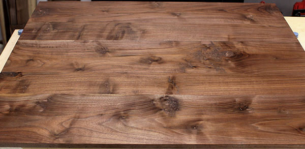
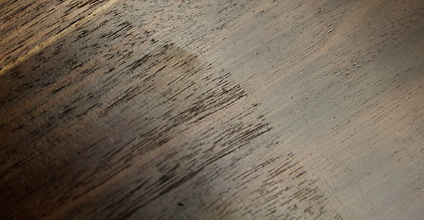
The photo below shows the dramatic difference in appearance between the smooth filled grain (right) and unfilled grain on the left. Both areas have two coats of wiping varnish.
For this shot, the camera was oriented to catch light reflected from the wood surface, so the grain pattern on the right is masked. Viewed with no reflection, the grain is clearly visible.
Final finishing involves:
-
Wipe with mineral spirits; allow to dry thoroughly.
-
Wipe-on shellac, which dries within minutes.
-
Sand with 400-grit sandpaper, because the shellac raises some grain.
-
Dry-wipe to remove sanding dust.
-
Wipe-on stain to subdue wood color variations; allow to dry thoroughly, usually 24 hours.
-
Apply three coats of wiping varnish, allowing 24 hours to dry. Sand with 800-grit sandpaper to remove any dust or bubbles. The final coat is not sanded, but is rubbed with 0000 steel wool if necessary to produce a matte finish.
November 21, 2013 – Cabinet hardware
Over the past several days, Mike made and installed cleats to hold the cabinet kick plate along the front, beneath the bottom shelf. Using cleats allows the kick plate to be attached from behind, eliminating all visible screws. The cleat is the light-colored block on the left corner of the side in the photo below.
Mike also milled the kick plate to its final size, filled the grain, and applied shellac and stain. It is ready for final finishing and attachment to the cabinet.
Today Mike installed the aluminum angle rails that will fasten the desk top and bottom shelf to the cabinet sides. He also screwed three drawer slides to each side. The cabinet is almost ready to assemble.

November 24, 2013 – Cabinet drawer slides installed
Oops! The drawer slide spacing turned out to be slightly off. Mike made a 1:1 scale drawing to transfer precise measurements to the wood. After several tries, he got it right. The spacing on the cabinet sides turned out to be okay, but the holes had to be re-drilled in the drawers. Mike installed slides on the cabinet sides, the two drawers, and the pull-out shelf (not shown in the photo below). The cabinet finally is ready to assemble, which probably will require both of us working together.
November 26, 2013 – Cabinet (mostly) assembled
Mike installed the remaining aluminum angle rails, then we assembled the bottom shelf to the two sides. We added a wood stick across the top to prevent the sides from spreading apart. Once the bottom shelf was secure, we turned the cabinet upright and added the drawers and pull-out shelf on their slides. After some minor adjustments to the front spacing, the cabinet looks pretty good, but a few more adjustments are needed.
November 30, 2013 – Detour! Bed Rails
Daughter Miranda's bed collapsed several weeks ago, and Mike finally took a break from building the desk to fix it. The frame rails are made of ¾" plywood, and two of the metal brackets that connect them to the headboard broke out of the rails. The plywood delaminated, and the brackets ripped out one side of the rail.
Mike and Miranda cut new ¾" oak boards to size, and machined 5/16" brass pins to hold the brackets in the ends of the boards. Then Miranda drilled blind holes for the pins.
The next day, Mike and Louise used the band saw to cut vertical slots in the ends of the 5"-tall oak rails. Later Mike pinned the brackets in place. He also used the same band saw fence setup to resaw one of the ¾" oak cutoffs into two 3/8"-thick planks, which he then planed to ¼" thick. He cut one plank into four 3" lengths, then used a belt sander to to bevel one end of each piece, and glued these to the outside of the rails to reinforce the wood outside the metal brackets.
Today Mike used a router to round-over the edges of the rails. Next he will fill the grain, sand, and spray-paint them black.
This photo shows the two new rails next to one of the broken original rails. Mike worked outdoors in 38°F temperature to eliminate router shavings and sanding dust in the shop. (He'll use a power sander to smooth the grain filler, which produces a lot of dust.)
December 10, 2013 – Cabinet top refinish
When we assembled the cabinet a week ago, we discovered the top was 1½" too wide. Sadly, the left edge already had a 1/8"-thick nosing applied, so cutting the top narrower put that nosing at risk.
We decided to try and salvage it. First we cut the top to the correct width on the table saw. Then we took the cutoff with the thin nosing to the band saw, and adjusted the fence to the nosing thickness. Amazingly, the band saw cut off the nosing precisely, and no further planing or sanding was needed.
Several days later, after Mike cut and attached the 5mm luan plywood cabinet back, he glued the thin nosing onto the left edge of the cabinet top. This resulted in a slightly uneven edge, which had to be scraped and sanded flush.
Naturally, the scraping and sanding damaged the varnish in that area. Mike noticed some of the sapwood grain was rough, so he took this opportunity to refinish the entire top. He scraped and sanded the panel, then applied grain filler to the sapwood areas. When this was dry, he scraped and sanded the wood smooth, applied shellac and stain, and spread three coats of wiping varnish. This work took four days, but the top now looks better than ever.
All that remains to be done is to rub it with 0000 steel wool to subdue the shiny finish, and attach it to the cabinet.

December 16, 2013 – Cabinet pullout shelf refinish
The refinished cabinet top turned out so well, we decided to refinish the pullout shelf, which had some of the same open grain as the top. Mike used wood filler to patch a few knot holes and gouges we missed the first time. Then he spread grain filler and, when dry, sanded it off. He followed this with a coat of shellac and stain. When the stain is dry tomorrow, he will apply several coats of wiping varnish.
Here is the pullout shelf with the top surface filled and sanded, ready for dusting and shellac. It's sobering to attack nicely finished wood with a scraper and 180-grit sandpaper, but we have confidence it will turn out fine, based on the top's result. The finished front of the shelf will not be refinished because it has the drawer pull glued in place.
Skipping ahead three days, here is the refinished shelf after the third coat of wiping varnish.
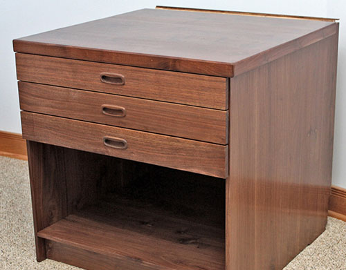
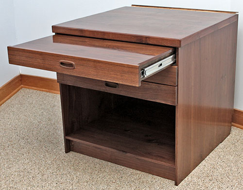
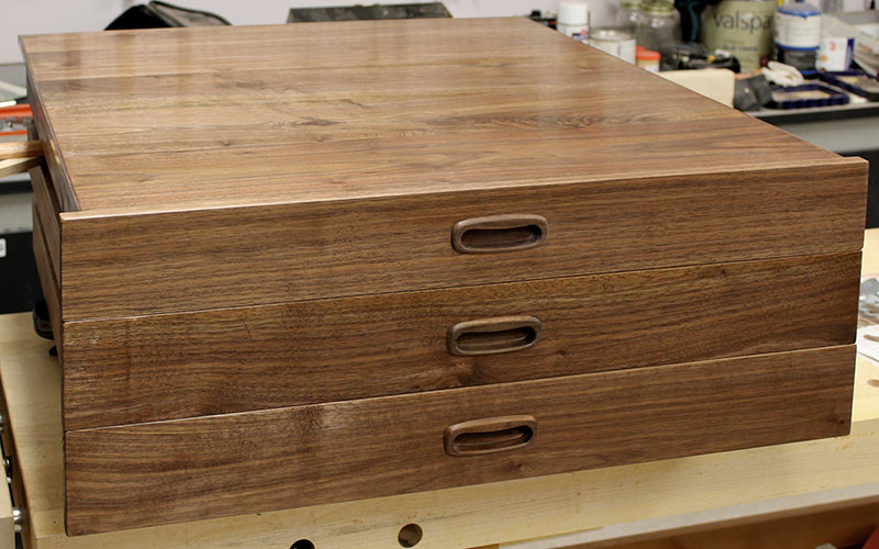
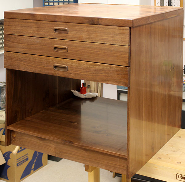
December 20, 2013 – Cabinet complete!
With the pullout shelf refinished and looking great, we put it on its slides, then moved the cabinet from the workbench into the hobby room to rest until the main desk top sections are finished. Here is the complete cabinet with all drawers closed, and with the shelf partially pulled out. (The odd-looking strip along the rear is the open cable tray, which ultimately will have a thin cover flush with the cabinet top.)
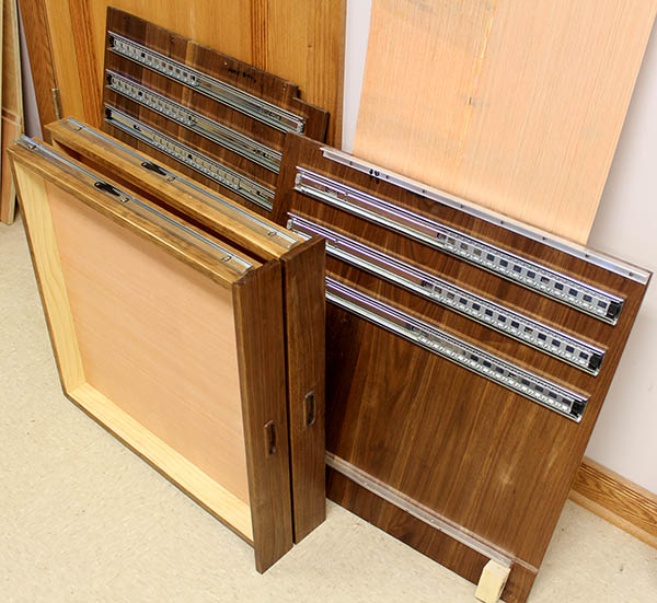
December 20, 2013 – What's left?
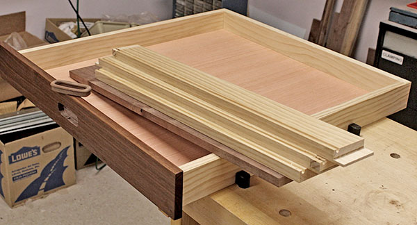
A friend asked how much was left to do before the desk is complete. The answer is, not much. This photo shows the remaining 10 pieces of walnut that will become the main desk top and the left extension. The single narrow board is one of two pieces for cable tray covers. Once the workbench is freed when we remove the cabinet, we will edge-glue these planks together, then smooth and finish them, and the desk construction will be complete. Following that, we'll need to install it in Mike's office, which will entail bolting it to the wall and fabricating one leg where the main desk top and the extension join.
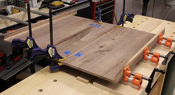
March 2, 2014 – desk top glued
Finally, after what seems like an eternity, we got back to work on the desk. We edge-glued the boards to make the 5' main desk top section and the short extension that will have its left end cut at an angle to match the walls in Mike's office.
Here are both desk top panels along with the nosings that will be applied to them. The three ¾ x 1½" nosings will be glued to the front of both pieces and to the left end of the extension. The three thin nosings will be glued to the ends of the desk top that adjoin each other and the cabinet.The short right-angled ends will be cut to match the profile of the large nosing.
The next step is to attach front-to-back bracing (aluminum angle and wood stringers) to the underside of both panels to add strength to the glue joints and ensure the desk top remains flat. Then we will glue the nosings, smooth the panels, and finish them. Finally, we'll glue cable trays to the rear of the desk top panels, and move the whole she-bang to Mike's office for installation.
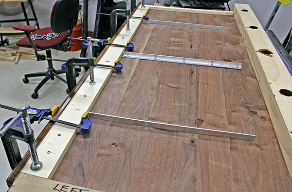
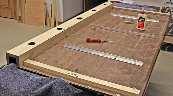
March 6, 2014 – desk top braced
Over the past few days, Mike added bracing to the main desk top and the desk top extension. We use ¾" aluminum angle for stiffness, supplemented by ¾" wood stringers near the ends. This photo shows the main section on the right, with three aluminum braces, and a wooden brace on each end, and the extension on the left with one of each. We need to trim the ragged ends of the extension at an 80° angle, then attach tthe second aluminum brace shown lying loose in the background.
Note: the extension is rotated 90° counterclockwise in this photo – its rear side is toward the left. The end with the clamps will adjoin the board on the far end of the main desk top. The near end of the main desk top will attach to the cabinet.
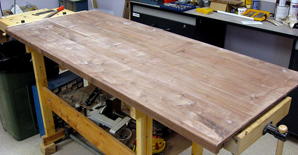
April 6, 2014 – desk top scraped
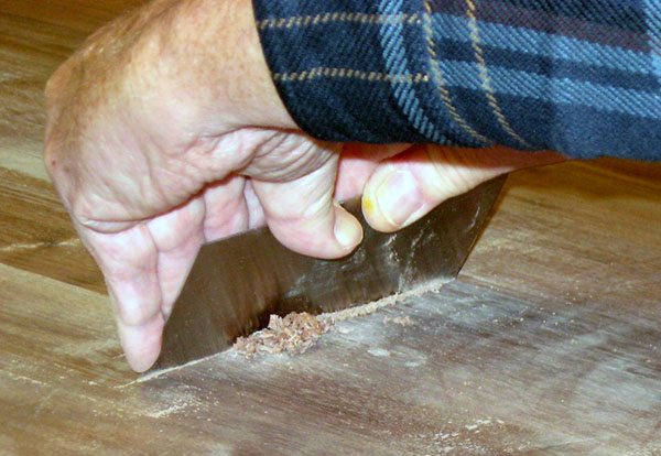
Mike has been scraping the main desk topsmooth over the past several days. This involves puling or pushing a rectangular metel blade held at a steep angle along the panel. Doing this scrapes thin layers of wood from the surface, leveling it, and removing humps or uneven areas.
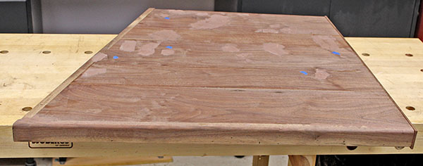
This photo shows Mike pulling the scraper, and the wood shavings it has removed. The large pile on the left side come from a glued section where the board is slightly high.
Here is the main desk top after scraping,almost ready for final sanding. Before that, a few blemishes remain to be filled with wood putty, then sanded level.
April 13, 2014 – Making a drill stop
Mike has scraped and sanded the main desk top to the point where it will be ready to finish after a few remaining patches of wood putty are sanded smooth.
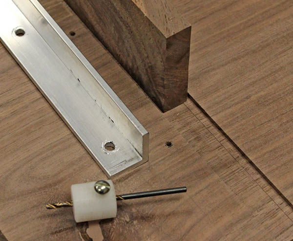
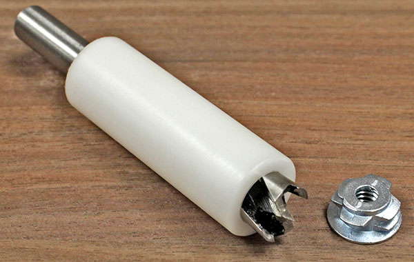
But first we must install metal inserts along the underside of the right end. These inserts thread into ½" blind holes in the walnut, and accept a ¼"-20 bolt. The desk top will fasten to a 1" aluminum angle on the left side of the cabinet, and bolts and shims will allow it to be adjusted to exactly the same level as the cabinet top.
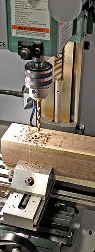
To avoid drilling too deeply into the underside of the desk top, Mike machined a drill stop from a length of Delrin. Here is a ½" Forstner bit in the stop next to an insert. The top of the Forstner bit rests against the top of the large end hole, and the stop's upper end butts against the drill chuck. The bit drills to the precise depth needed.
April 14, 2014 – Making another tool
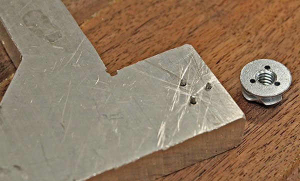
The bolt inserts for the desk top must thread themselves into the wood. They are quite thin, so there are no flats for a wrench – only three holes in a triangle.
Mike made a wrench to install the inserts. He found a scrap piece of ½" aluminum, and drilled three holes to match the pattern on the insert. Next he counterbored shallow holes slightly smaller than the brad head. Then He cut three brads to 0.55" long, and filed the cut end smooth. He drove the brads into the three holes, pounding their heads into the counterbored holes, flush with the top surface.
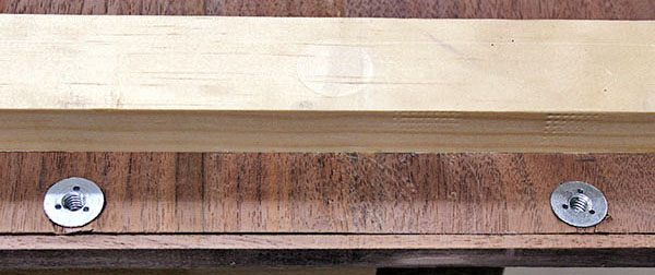
This is underside of the wrench, with the three brads protruding. They fit the insert perfectly, and are short enough to allow the insert to rest flat against the tool. This is important because we'll need to apply pressure as we rotate the insert, so its teeth cut threads into the walnut.
April 16, 2014 – Inserts installed
Today we installed four inserts into the right end of the desk top. Sadly, Mike's tool didn't work as expected. We were unable to apply sufficient pressure to cause the insert to thread its way into the wood.
Louise came up with the idea to thread a bolt with a jam nut into the insert, then use a wrench to turn the nut while pressing down on the bolt. This worked very well, although keeping the bolt perpendicular to the wood was tricky. We had to use a C-clamp to apply sufficient pressure to one insert – it didn't want to start threading.
Mike removed the brads from his homemade wrench, then tossed the piece of aluminum back into the scrap bin.
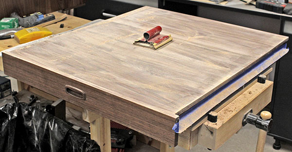
April 22, 2014 – Stain and first varnish
After several days of repeated grain-filling and sanding, we decided the desk top is good enough, even though a couple of small areas still seem to have open grain.
Yesterday evening, we applied stain over the surface. 24 hours later it was dry, so Mike applied the first coat of wiping varnish. (This photo shows the varnish still wet. It dried to a satin sheen.)
Three more coats, with sanding in-between, and this major piece will be finished, except for gluing the cable tray onto the back edge.
April 27, 2014 – Cable tray
After allowing the first varnish coat on the main desk top to dry thoroughly for several days, we prepared to install the cable tray. First we laid towels as padding on the workbench, and flipped the desk top unside-down.
Next we drilled seven holes for mounting screws through the 2½"-high front wall of the tray, then drilled 1½" holes in the bottom for cables to pass through. Mike applied stain to the tray interior and the sides of the large holes.
Mike used screws to mark the corresponding hole locations on the desk top, then drilled those holes. He ground off the screw points so they wouldn't break through the desk top.
Finally, he spread glue and fastened the cable tray to the desk top, using a machinist's square to ensure the tray is perpendicular, because the wall brackets to support the desk top will attach to the bottom of the tray.
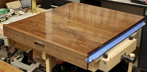
April 28, 2014 – Varnishing the desk top
We flipped the desk top right-side-up, and Mike applied the second coat of wiping varnish to it.
April 30, 2014 – Varnishing the desk top
Mike applied the third coat of wiping varnish to the main desk top. One more coat to go.
May 1, 2014 – Varnishing the desk top
Mike applied the fourth (cnd hopefully the final) coat of wiping varnish to the main desk top.
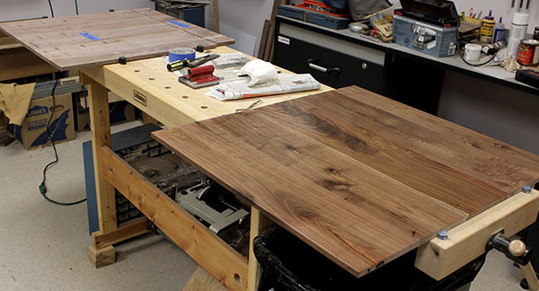
May 2, 2014 – Main desk top complete
The fourth coat of varnish dried nicely, and we declared the main desk top complete. Mike carried it into the room where the cabinet and hutch are waiting, and set it up for show (this room is not Mike's office).

Alas, the aluminum angle rail on the cabinet side that supports the desk top is slightly too long, preventing the the threaded inserts on the underside of the desk top from aligning with the holes in the rail. We'll remove the rail and cut off 1/8" so the desk top can slide forward.
The next step is to smooth and finish the desk top extension, shown below. Following that, we will fabricate a leg to support the left-front corner of the main desk top. The carton now supporting it causes Mike to wonder if we should make a base unit with three deep drawers, instead of using a leg.
May 3, 2014 – desk top extension
Mike scraped and sanded the short desk top left extension. He filled the remaining holes and gouges, then sanded it smooth. Later he sanded it once more, than spread grain filler, and brought it inside to dry overnight.
May 4, 2014 – desk top extension
Mike sanded excess dry grain filler from the desk top extension, then applied a coat of shellac.
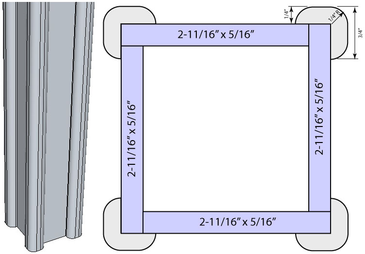
May 4, 2014 – desk top leg plan
We decided to make a 3" square leg to support the left-front corner of he main desk top, instead of building a drawer base unit. We can build the base later if Mike finds he needs additional drawer space.
This is the leg we plan to make.
May 9, 2014 – desk top extension
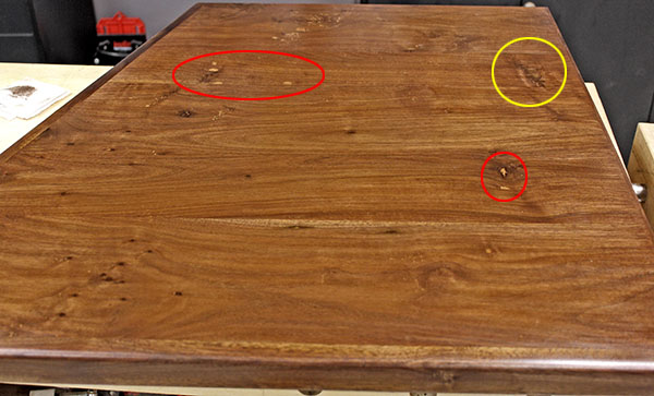
Several days ago Mike applied a coat of stain to the desk top extension. When that dried, it was apparent some grain wasn't adequately filled. So he sanded-off the stain, then applied another layer of grain filler. The next day, he sanded off the excess grain filler, and applied a new coat of shellac. Following this, he wiped on stain.
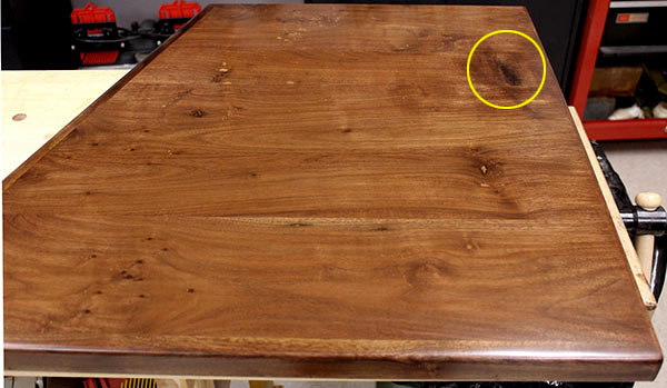
The walnut used for this panel had some gouges we filled with wood filler. The filler is lighter than the surrounding wood, even after staining. This photo shows three patches (circled). Two (red) have the same stain as the entire panel, but Mike stained the large patch darker (yellow). He cut a hole in a sheet of paper to mask the surrounding area, then gave it a quick shot of spray stain. The result is passable, but we might decide to touch it up or re-do it entirely.
May 11, 2014 – desk top extension
There is no need to touch-up the large stained patch. Judicious rubbing with 000 steel wool removed excess stain and blended the patch into the surrounding area. It turned out darker, but it's not splotchy, as in the photo above. Mike applied the first coat of wiping varnish yesterday, and the second coat today.
May 14, 2014 – desk top finished
Yesterday Mike wiped the fourth and final coat of varnish onto the desk top extension. Today he attached the cable tray, and carried the extension to the rest of the desk, to see how it looks.
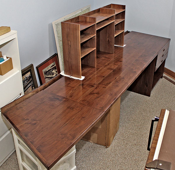
Here is the full desk in all its glory. the main desk top and the angled extension are temporarily supported, but at least we see how it will look.
Mike needs to fabricate a leg and finish the cable tray covers, and then we can install the desk in his office.
May 15, 2014 – Leg, first steps
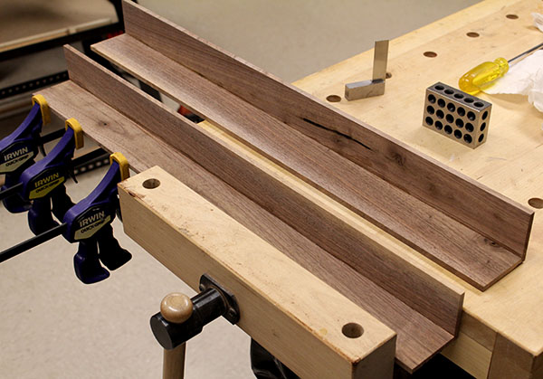
Mike started working on the desk leg. He found a couple of leftover walnut boards 27" long that were only slightly warped. He ripped these to 2-3/8" wide, then surface-jointed and planed them to remove the warp. He used the band saw to resaw each piece into two 3/8"-thick planks, then planed these to a final thickness of 9/32" – only 1/32" thinner than the plan calls for.
Next Mike glued a pair of planks together, checking the angle with a machinist square and 1-2-3 block. When the glue dried on these, he glued a second pair. The next step is to glue both sections together to make the square leg. After that he will cut and shape the rounded corner moldings (see the leg plan above).
May 16, 2014 – Leg glued
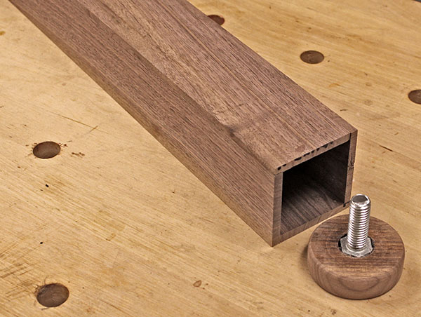
Mike glued the two leg sections together to make a square column. When dry, he planed the four surfaces smooth.
Mike also made an adjusting foot by using a hole saw to cut a 2½" diameter "puck" from ¾" walnut. He counterbored a hole for the head of a ½" bolt, and affixed it place with Goop adhesive.
Ultimately the leg will contain a pine insert holding a nut for the bolt to screw into.
May 17, 2014 – Leg height adjuster
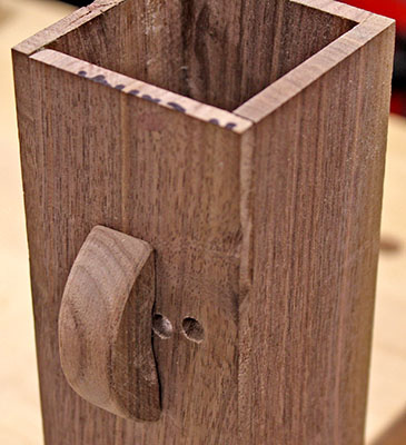
Change of plans! Mike didn't like the idea of the height adjuster "puck" holding the leg off the floor, so he designed a height adjuster for the top of the leg.
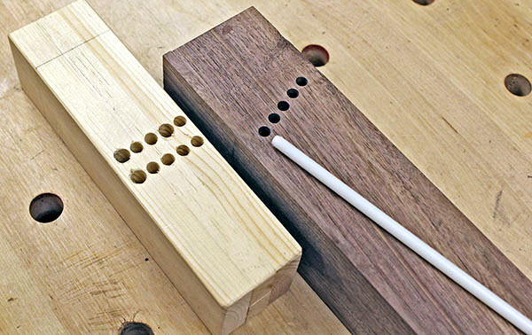
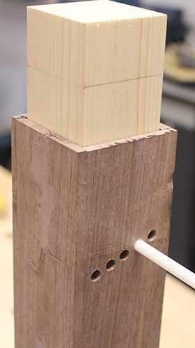
As shown animated here, a square post slides inside the leg column. two rows of five ¼" holes are drilled in the post, and a sloping row of five holes are drilled in the leg. A ¼" steel pin inserted through the aligned holes holds the desk at one of 10 positions, providing an adjustment range of 1-1/8" in 1/8" steps.
Later Mike fabricated most of the parts for the new height adjuster. He cut, planed, and glued four pine pieces to make the square post that fits inside the leg column (the short length shown to the left will fit inside the leg at the bottom to add strength). After careful final planing, it slid smoothly. It's not as precise as machined metal pieces would be, but it's good enough. Mike also made four flange pieces that will attach the top post to the desk top.
May 18, 2014 – Leg height adjuster complete
Mike drilled the holes for the leg height adjuster, using the milling machine in the metalworking shop. These photos show one of the drilling operations (left), the finished parts (center), and the assembled height adjuster (right). The pin to fix the height is ¼" Delrin rod; ultimately we might use steel.
Notice some holes in the pine post are larger than others. Even with the precise positioning afforded by the mill, some holes in the post did not align with their counterparts in the leg column, and had to be enlarged.
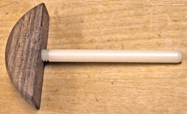
May 19, 2014 – Leg height adjuster pin handle
Mike cut off a slice of the no-longer-needed adjustment foot "puck" (see above) to make a handle for the ¼" Delrin rod that locks the sliding post at the desired height. He sanded it to shape, then drilled and tapped a ¼"-20 hole. He used the metal lathe to thread one end of the rod, and screwed it into the handle.
Now it's easy to insert and remove the rod. We'll need to cut notches in the corner molding when we install it, to allow clearance for the handle with the rod in the outer holes.
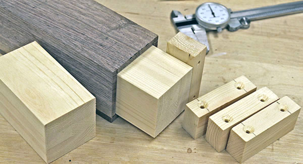
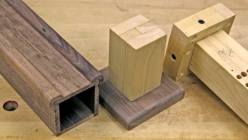
May 20, 2014 – Final leg parts
|
Late yesterday Mike attached four mounting flanges to the leg's top (adjustment) post. Today he fabricated corner molding and a base plate for the leg. Here are the results.
On the left, two lengths of molding rest on the leg. These were cut from ¾"-square walnut. The center ½" was removed, leaving an "L" shape. Three edges were rounded to a ¼" radius.
The leg base is in the center. a 4"walnut square has its top edges rounded to a ¼" radius. A short pine post is attached to the base, and will be glued into the leg.
The top post is on the right. Pine flanges are drilled for eight screws to attach the post to the underside of the main desk top.
It was a successful day. We need to cut the leg column to length, trim and sand the molding, and finish everything. Then it's on to the cable tray covers.
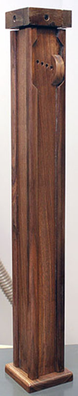
May 29, 2014 – Planning the cable tray covers
The leg is finished (photo right).
Mike moved the desk top and extension into the shop to begin fitting the cable tray covers.
The cable tray covers must be cut into short sections, with a round hole for cables at each joint. Mike began planning how to cut them, but Louise advised against this until the desk is installed and Mike knows where the hutch and computer monitor will be placed.
Then mike worried the hutch might not sit far enough back on the desk top to allow removing a cable tray cover. So he made some ¾"-wide wood strips to glue to the rear of the cable tray, to allow the hutch to be placed farther back. These might not be needed, but if so, at least we'll have them.
|
|
May 31, 2014 – desk top tweaks
Yesterday Mike added a 3/16" ledge to the cable tray (left) to provide more support for the cover. Somehow the tray ended up wider than intended, so the cover was barely supported, and could easily fall into the tray. The ledge provides more support.
Mike also added a pine 1x3 along the front of the main desk top to stiffen it (right). The top deflected slightly with only moderate pressure when we temporarily placed it in position. Hopefully the 1x3 will stiffen it adequately.
June 4, 2014 – desk top warp
A few dqys ago Mike discovered the left end of the desk top is warped front-to-back – it humps in the center, and is lower in the front and back. This isn't very noticeable when looking at the top, but the downward warp in the front caused the leg to tilt 1°.
We decided to remount the leg attachment bracket with a shim to correct the tilt. Mike hammered a putty knift under the bracket to break the glue bonds. We measured the thickest shim needed, then Mike made one by scraping and sanding a 1½"-wide length of thin pine to taper to a knife edge.
This photo shows the warp beneath the straightedge (which is resting on an oak 1x3 used to attach the desk top extension). The remounted leg is toward the left.
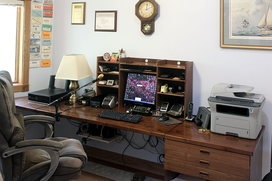
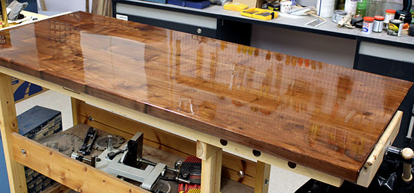
July 16, 2014 – Complete!
The desk is complete! We installed it in Mike's office three days ago, and Mike has been setting up and arranging his office and amateur radio station ever since.
The desk looks great. The boards on the three top sections were cut from 10' planks, so the grain pattern runs continuously from one section to the next. The finish is smooth as glass.
It took us over a year to build this monster, but the result is worth the effort.
Updated
May 23, 2023