When we built the house, we laid heavy-duty electrical cable in a trench to a 4x4 post at the observatory site. We will wire the observatory for electricity with regular Romex cable, switches, and receptacles, and connect it to a weatherproof breaker box mounted on the post.
The trench also has two CAT-5 cables for Ethernet connectivity to the home network. The second cable was originally intended for telephone service, but now is reserved as a backup Ethernet cable.
Yesterday Mike dug a 10-foot 6"-deep trench to the observatory from a 4x4 post holding electricity, water, and Ethernet. Today he laid ½" PVC conduit from the post to the building.
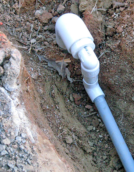
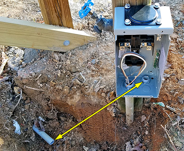
This task was complicated by the need to connect the in-ground conduit to fixed points on the observatory. Also, one goal was to replace a 1¼" Ethernet conduit and weather head sticking out of the ground next to the 4x4 post with the ½" underground conduit.
Mike cut off the 1¼" conduit, and used various elbows and bushings to attach the ½" conduit to it. He had to feed the two CAT5 cables through each elbow and bushing individually before cementing them together. Here's a photo of the result. The entire assembly will be buried.
Our original plan called for the observatory to plug into a GFCI receptacle on the nearby 4x4 post, but this has changed. Now, a ½" conduit will hold a 12-gauge cable wired to a weatherproof breaker box on the 4x4 post. The observatory end of this conduit will run to a PVC junction box screwed to the bottom of a floor joist.
Three ½" conduits will run from this box to boxes on two walls and the concrete pier. 12-gauge Romex will run through the conduit to feed power to receptacles at these locations.
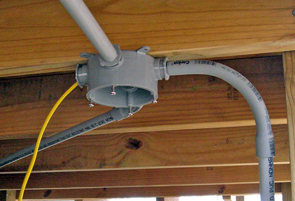
Before the rain began, Mike installed conduit from the central junction box to the middle of the west wall and to the northeast corner of the east wall. This photo shows the box with the two branch conduits and the curved conduit from the breaker box.
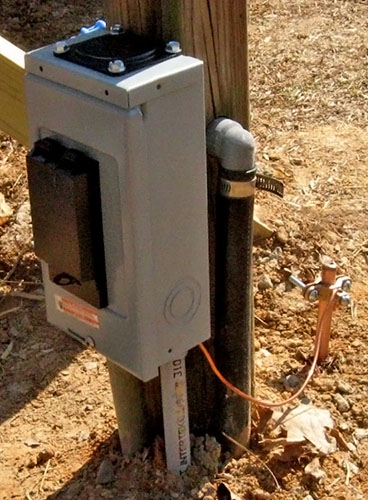
An expert on AC power wiring convinced Mike to connect the cable from the house to a circuit breaker in a weatherproof box just outside the observatory, and grounded to an 8-foot rod driven into the earth.
With a local breaker, the observatory is protected better than wired to a breaker 300 feet away inside the house.
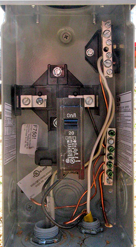
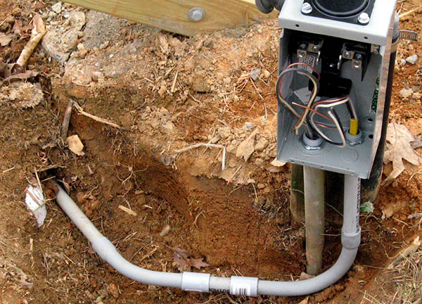
Today Mike extended the conduit from the junction box under the observatory to the breaker box, then pulled 12-gauge Romex through it, and connected the wires to the appropriate points in the box. This photo was taken before the wires were connected and the trench backfilled.
Mike also ran conduit and pulled Romex from the west wall to the pier. A non-GFCI receptacle will be mounted on a 2x4 projecting from the pier's square hole in the floor, and wired to the west wall box with a GFCI receptacle.
Yesterday Mike drove an 8-foot ground rod into the earth, and today he connected the ground wire from the breaker box to it. He installed the breaker, fastened the cover, and called this task complete.
|
|
|
Next, Mike pulled Romex cable through the conduits from the central junction box to the east and west walls, then installed plastic electrical boxes inside. The wiring is complete and ready for the receptacles and switches to be connected and installed.
When not interrupted by rain or snow over the past nine days, Mike finished wiring the observatory. He installed all receptacles and switches, and connected the branches together in the junction box under the floor
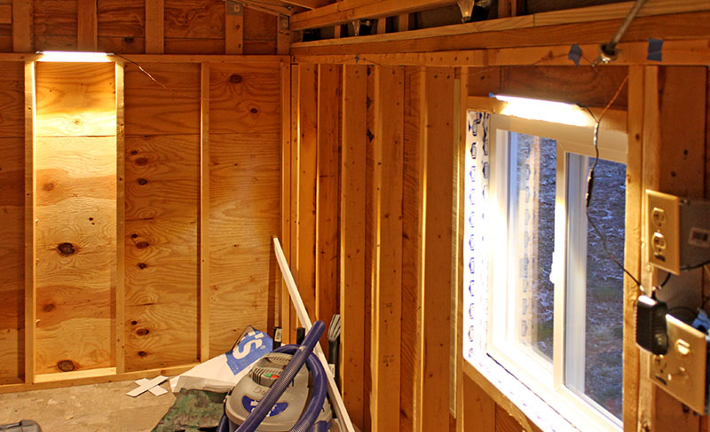
Today he extended the cables between units of an LED under-counter light system, and taped the lights temporarily in place to see how well they illuminate the interior.
This photo shows two of the three LED lights, one above the west window, and the second on the south wall. The third light is out of view on the north wall. Two switches by the door control two adjacent duplex receptacles, one for the interior lights, and another for a small exterior LED "porch light."
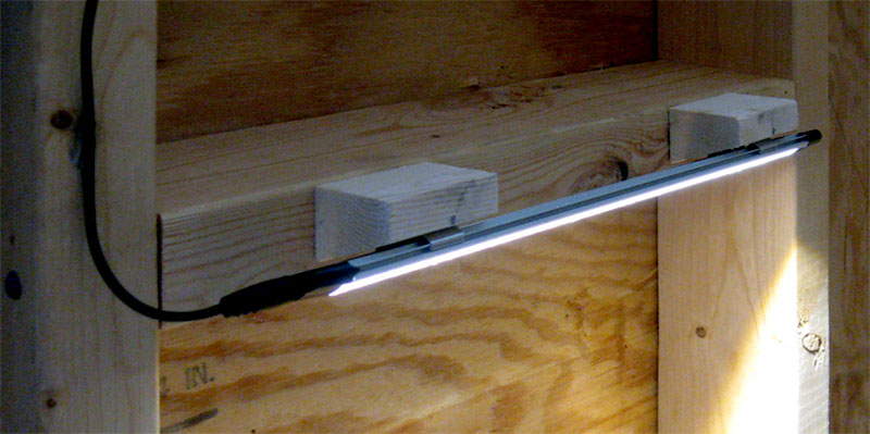
Mike cut six blocks with a 20° angle to attach the three LED lights to the walls. He glued the twisted-pair extension cables to the walls with Goop, and declared this job complete. Here is one light and its mounting blocks.
Mike installed the computer desk he made several weeks ago. It's in the northeast corner, 44" above the floor for convenient stand-up use.
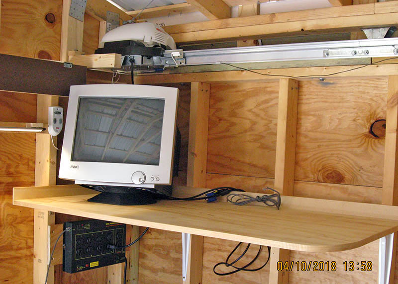
Mike brought the Windows 7 computer to the observatory and set it up on the desk. He connected the monitor and verified that everything works, including network connections.
He still needs to make an enclosure for a terrarium heater to warm the computer on cold nights so it starts reliably.
Mike plugged the Ethernet cable running from the network closet in the house basement into a 5-port switch, and confirmed a good connection. It's been three years since he first checked out the Ethernet. Happy to see it still works.
Mike also installed an Ethernet power controller similar to this one under the desk on the north wall. It uses commands sent over Ethernet to switch AC power to eight receptacles, so we can turn on and off individual pieces of equipment from inside the house.
A second 8-port switch will be installed by the telescope pier to control power to devices located there.
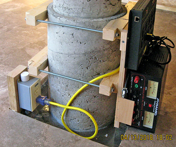
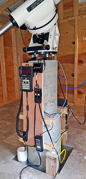
Over the past couple of days, Mike made a bracket to mount certain equipment near the telescope. It has four wooden jaws that clamp to the 12"-diameter lower portion of the concrete pier, and also provide mounting points for shelves and hooks as needed.
As seen in this photo, the south jaws hold the second Ethernet power switch above a DC power supply for the telescope mount. The north side will hold the focuser's power supply and controller, plus the mount's hand controller.
A critter screen keeps out rodents, snakes, and other curious animals (but not bugs, which come in around the roll-off roof). The screen also catches small parts that drop while working on equipment at the pier. It is attached with construction adhesive to the pier and to the sides of the floor hole.
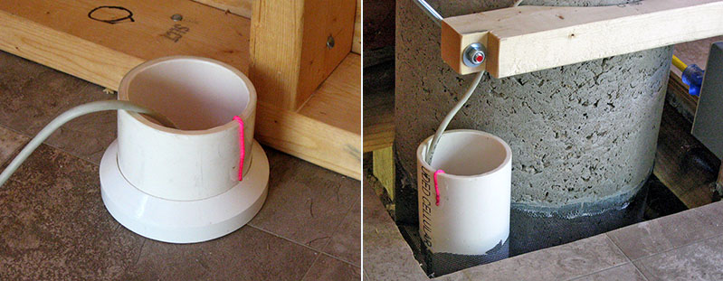
At Louise's behest, Mike modified a PVC reducer fitting to make a collar for the 3" cable conduit emerging from the floor under the computer desk. It looks nice, but required an inordinate amount of work for such a small benefit.
Mike pulled a "messenger string" through the conduit from the computer desk to the pier. This string has a center loop to allow cables to be attached and pulled through the conduit in either direction. The string is glued to the outside of the conduit on both ends.
The right photo shows the conduit at the pier.
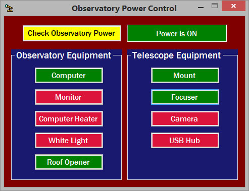
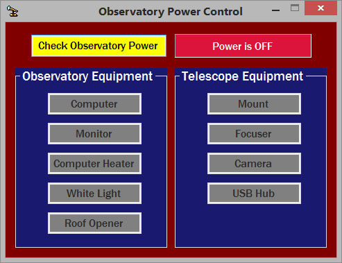
While waiting for the sky to clear so he can finish aligning the telescope, Mike wrote a computer program to control two Ethernet power switches in the observatory, one by the computer desk, the second by the pier. All equipment in the observatory gets power through these switches.
Clicking a device's power button sends a command over the network to switch power to that device. These buttons are green when on, red when off.
|
|
Clicking the yellow button at the top "pings" one power switch to determine if observatory power is on. If not, all other buttons are disabled (right photo).
The software executes a request to turn off the computer's power only if the computer has been shut down (does not respond to a ping). If the computer is running, the power-off request is ignored.
Power to the entire observatory is controlled with a wall switch in the basement shop, but Mike can turn that on and off with a pushbutton in his office that sends X-10 signals over house wiring to the basement switch. Our solar power system interferes with the X-10 signals when the Sun is shining, so then Mike has to walk down to the shop to throw the switch.
Mike installed a tall piece of plywood on the north side of the clamps around the concrete pier. A hook holds the mount control box at the top-left, and industrial-strength Velcro holds the focuser control box and related small items on the right side. A USB hub occupies the lower-left corner.
Updated May 23, 2023